|
|
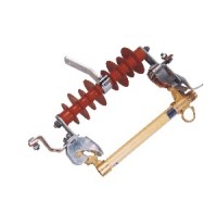
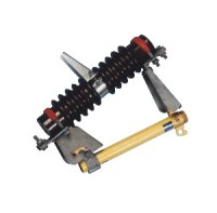
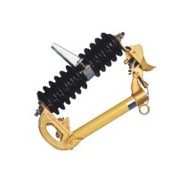
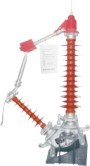
GW9-10 outdoor high-voltage isolation switch
Collect
商品说明
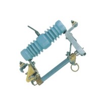
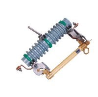
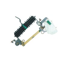
1、 Purpose: (H) GW9-10 outdoor high-voltage isolation switch is a single-phase AC 50Hz high-voltage switchgear used in power systems with a rated voltage of 10kV to connect or isolate power sources under voltage and no-load conditions. This isolation switch is operated using an insulated hook rod. 2、 Usage environment a. Altitude not exceeding 1000 meters; b. Surrounding air temperature: upper limit+40 ℃, lower limit -30 ℃ in general areas, -40 ℃ in high-altitude regions; c. The wind pressure shall not exceed 700Pa (equivalent to a wind speed of 34m/s); d. The seismic intensity shall not exceed 8 degrees; e. Places without frequent and severe vibrations; f. Ordinary installation sites should be free of gases, vapors, chemical deposits, salt spray, dust, and other explosive and corrosive substances that seriously affect the insulation and conductivity of isolation switches. Anti pollution type is suitable for heavily polluted areas, but should not contain substances that can cause fires or explosions. 3、 Structure and working principle This isolation switch is a single-phase structure, with each phase consisting of a chassis, pillar insulators, switches, contacts, and other components. The side of the switch blade has screws for adjusting contact pressure and springs for compression. The upper end is equipped with a fixed pull buckle and a self-locking device connected to it, which is used for opening and closing the insulation hook rod. This series of products has the advantages of large contact area, low contact resistance, good conductivity, and high mechanical strength compared to unimproved products in terms of structure. 4、 Product installation This isolation switch is generally installed in an inverted manner, and can also be installed vertically or obliquely (with the moving contact below). The chassis is fixed in a suitable position on the crossbar with M12D bolts, which should be convenient for pulling and closing the switch blade on the ground with a lever hook, and ensure that the chassis will not loosen during operation. The incoming line should be connected to the static contact side, and the outgoing line should be connected to the dynamic contact side. The appropriate distance should be maintained between the three-phase switches to avoid short circuits.
相关商品
|